|
Sprache |

 |
|
|
SuperSTacy Disclaimer | 02.08.02 maanke | ATTENTION
Please read this text completely and carefully before(!) you start
working, so that you can appreciate if you will have the skills or not!!!
Some years ago there was a discussion in german MouseNet, where Steffen Engel reported
that he had soldered a PAK/3 into his STacy
so I planned to build a SuperSTacy, too, because I had a jobless STacy
lying around in a corner.:)
One thing first, everyone who wants to do the following should have very good solder
and desolder skills, because fitting the PAK into the STacy is not easy. If you have two left
hands, keep them off from it and ask someone who can do it for you, because even with a left and
a right hand it is everything else as simple.
I will take no responsibilities in any way, if you damage something,
when tuning your STacy!!
In addition I will not answer any questions that deal with this conversion, this text is only for
solder artists and should only make things easier.
Emails to this subject will be deleted unreaded!
The project is nothing for someone who wants to rebuild his STacy to it's origin
condition some time, because we will be rather rabid to the case of the STacy:)
You should take enough time for the conversion and be very careful, you will not do it
during your lunch hour!
I will describe some things, I got from some hypertexts I collected, so that I will not
describe all things precisely and give only the sources, because not everything in this
text I have made myself and are copyrighted.
In detail I will describe how you dismantle your STacy (this is enough for a
single article;-), repositioning the power supply, installing the PAK and installing
a bigger hard disc.
|
|
SuperSTacy Tools | 02.08.02 maanke | First you should get your tools, essential are the following things:
Tools:
Circuit analyzer!
Thin soldering iron
Thin tin solder
Desoldering pump
String cutter
Various screw drivers
Pliers
Hot glue pistol
Parts:
64-pin precision socket
Headers and sockets
5V positive regulator 2A (78S05)
Possibly parity generator (74F280)
Possibly 33 Ohm resistor
Various braided wires
Other:
Tape resp. insulating tape
Possibly shrink tubes
Pasteboard
Nerves
Calm hands
|
|
SuperSTacy The secret of the STacy | 02.08.02 maanke | **** First of all separate STacy from electrical power ****
Then turn around STacy und remove all cross-notched screws from the bottom, furthermore
the screws on the back of STacy, after that turn around the STacy again.
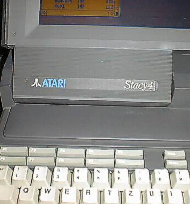
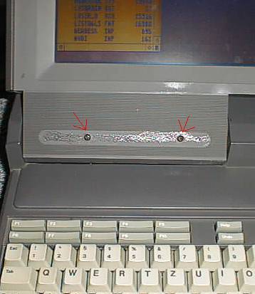
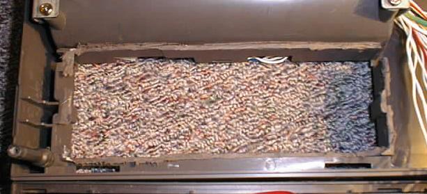
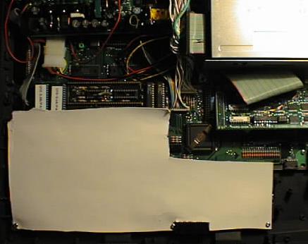
The great secret to open the STacy is the sign on the inner side of the display (look
at the pictures), you should safely remove it with a pointed object and put it in a safe place,
you can put it in place again, when finished. Under the sign are two cross notched screws,
that you should screw out (red arrows). After that you can safely try to remove the display
cover with a screw driver, if you use to much force the plates inside the display will break,
if you use not enough force you won't be able to remove the cover.:)
| The secret of STacy |
|
|
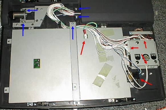
Now you have the interior life of the display in front of you, first you should remove the
bar which is screwed from top to bottom of the display (see pictures, everything that should
be screwed out is marked with blue arrows). Now remove all cables that are coming from the right
out of the case (red arrows), on my STacy it was no problem to remove the cables without
remembering where they were, all plugs were different and could only be plugged in one direction.
Perhaps this is different on other STacy models, so look carefully if you better should
write it down.
Now you can remove the two screws of the hinge, which is also the lead-through for the display
loom, it's also a good idea to remove the left hinge so that you can remove the complete display.
But, be careful, remove the screws only when the display is closed, spring tension!!
After that you can carefully remove the whole top cover with the display, again with the screw driver technique I
described above. The cables could now removed easily through the hole and you can remove the
whole cover.
|
|
SuperSTacy Disembowel STacy | 31.10.01 maanke | ATTENTION: Now follows another obstacle, where you have to be very, very careful,
disconnecting the keyboard!!
The keyboard is connected with a little foil to the daughterboard, this little piece of
plastic contains vacuum-metallised circuit pathes and should in no case be broken! If you
break this little piece of sh... your STacy is nearly ready for the garbage can, because
it's almost impossible to get a new one!!! Perhaps you will be lucky at
Best-Electronics, so you have been warned!
Lift of the keyboard carefully at the rear edges and flap it forward, then carefully pull the
lock of the keyboard plug forward, grab the foil where it's thickened, and only there(!), and
pull it out, put the keyboard upside down (foil is looking up) in a safe place.
On the image you can see the keyboard plug, you can see how to handle the plug. Further on you
can see that the fixations of the strap are screwed out, this makes it much easier to put in the
keyboard foil later, when reassembling the STacy
O.K., hardest part is done.:) Now remove the metal shield, unplug the floppy and harddisc and
screw out the case where floppy and harddisc resides and take it out carefully.
Now you have the open STacy lying in front of you and you can take carefully out the power
supply and the "SCSI-Host Adapter". But for getting out the PSU you have to desolder the
cables from the power switch, furthermore you have to unplugg the plug that goes to the LC-Display,
don't forget, under no circumstances to plug in this cable again when testing STacy!!!
Underneath the PSU resides black and with 64 pins the 68000, we will pay attention on him later.
Finally you have to remove some screws, take out the trackball with the same method as the keyboard
and take out carefully the whole circuit board.
|
|
SuperSTacy Handle the battery case | 31.10.01 maanke | But, before you rock your solder iron, there is some tinker work to do, first you have to cut
the battery case out of the top part of the STacy case, because the power supply will
go to this place later. To whom of you who think, that you want to bring your STacy later to it's
origin condition, I will say that that Atari never produced an accumulator or battery pack and by the way with such
a battery pack STacy wouldn't run very long, so cut it away.;)
(see image)
I used a little 12V drill with a cut-off wheel to cut it away, but you may have your own method
to do it.:)
|
|
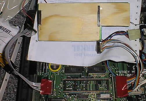
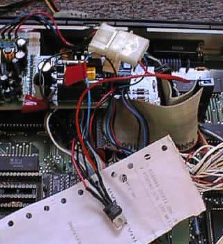
SuperSTacy Displacing power supply | 31.10.01 maanke | After you have knocked off the plastic dust and excused your nose from it, you can amuse
yourself with the power supply. So that the power supply does not produce a short circuit
you should isolate the underside with a piece of cardboard or plywood. Furthermore I recommend
to put an adhesive tape around the circuit board of the power supply so that no cables or whatever
can go between cardboard/plywood and circuit board.

Underside of PSU plywood board.
Now you take a socket that will fit to the header of the PSU and a header that will fit
to the socket on the STacy board and connect them 1:1 with cables (approx. 0.5 square mm)
that are long enough to put the PSU in the new place later.
Another possibility is to solder out the the headers and sockets from the board and PSU and solder
the cables directly to them.
Be very carful when doing it, measure all cable connections very conscientiously and look for
possible short circuits, if you make a mistake with these cables this can be very fatal to the
STacy mainboard, effect is: STacy --> garbage can!!!
Now we will test if PSU is powering everything, for it you first put in the
daughter board and connect the LC display again, important is that you really connect all
cables of the display, mainly the little 2-pin plug that is plugged to the power supply!
Plug in the header and socket cables to the board and PSU, pay attention to look for the
right order!! You should isolate the headers and sockets with some adhesive tape. It's not
necessary to connect the keyboard and trackball for this test.
Then solder the cable again to the power switch and check once again if everything is in the right
place and connected!
Now you can power on the computer, after a short moment the display of STacy should become
bright, if nothing happens power of STacy immediately and check everything again.
Are there vertical stripes on the display the connection between board and PSU is not correct,
measure it again carefully.
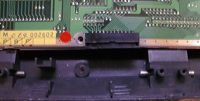
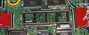
If everything works alright, dismantle everything again, then bend the socket pins on the board
to about 45 degrees, best the left one to the left and the right one to the right, otherwise
PAK will not fit on processor socket. If you soldered the cables directly to the board this isn't
necessary.:-)
You can do now again a little test if everything works and when it does, dismantle everything again
and get out the board completely from the case.
Connection PSU - mainboard (between it you can see the processor socket)
|
|
SuperSTacy Desolder processor | 31.10.01 maanke | This work is for the Terminators of us.;^)
There is more than one possibility to remove the processor, the most safely method for the
motherboard is the most destructive for the processor, but that is not so bad as it sounds,
a 68000er processor costs about 5$. In times when 68000er costs much more money I have
desoldered it from a 520ST without killing him, but some solder pads were ripped off and
I had much fun to repair them.:-/
In this place I will describe the destructive method anyway. You take a little edge cutter
and cut off every pin of the 68000er, after that desolder all pins with the help of a
desoldering pump and pay attention that all pads are freed from solder and pin fragments.
If you were successful you now can solder the 64-pin precision socket to the place where the
68000er was.
Take care that soldering times are not to long, to not damage the mainboard.
Before attaching the speeder to the socket, you should cut out, for isolating purposes,
a piece of cardboard and glue it to the bottom of the PAK.
Now you can attach the speeder carefully, important in this place is, you have to ensure
that you have a TOS 3.06 on your PAK/3 (see
see documentation of your PAK) because STacy only have TOS 1.0x, otherwise STacy
will not boot
There's also the possibility to attach any other speeder board that fits to the 64-pin
CPU socket.
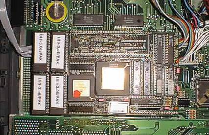
The PAK attached to STacy
Now put all cables again in it's place and test it again.
|
|
SuperSTacy Floppy troubles | 31.10.01 maanke | When a speeder is fitted it is possible that the STacy crashes when accessing the
floppy drive. This is a problem of the voltage feeding, the +5V (red conductor) branch is not very strong, so
that a floppy access results in a fall of voltage. But there is a workaround, for it you need
the 78S05 (see picture) voltage regulator, with this you can generate the +5V from the +12V (blue conductor) branch.
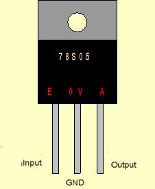
Solder into the +12 V conductor (blue) of the harddisk power the input of the voltage regulator,
the black cable goes to GND and at the output of the voltage regulator you got +5V.
Furthermore I have isolated the regulator with some shrinking tube from the surrounding area.
Besides I have put a Y-cable to the harddisk power supply, so I can take the +12V for the
regulator from a plug and have an extension to the harddisk.
(see image).
If this is all what you need you can reassemble the STacy or bring it to the hazardous waste,
depending on how successful you were.;-)
|
|
SuperSTacy Replacing harddisk | 31.10.01 maanke | In an original STacy you will find a 30 or 40 MB harddisk, which is even for Atari conditions
to small today and why not replacing the harddisk when the case of STacy is just open.
If it were so simple.:(
The SCSI card that is fitted to the STacy has not deserved this name, by the way it's
the same that is fitted to the MegaSTe, you're a little bit reduced in the choice of the
harddisk, and the connection of the harddisk is not as you know it from normal SCSI busses.
Some facts about the STacy host adapter:
1. You can only attach one harddisk
2. The SCSI ID has to be always 0
3. The disk must not be terminated
4. No parity
5. No initiator identification
6. max. 1 GB
Especially point 4,5 and 6 are difficult to solve with modern harddisks, you have two choices,
either you search for a harddisk where you can disable parity with a jumper (difficult) or
you fit a parity generator to the SCSI host adpater, for it you need the 74F280 you, I quote
from Michael Ruge's Chips'n Chips hypertext:
                   The modification
     Bend the pins 1-7 and 8-12 of the 74xx280 sideways up, bend pin 13
     a little bit to the FRONT, so that it get in contact with pin 14.
     Now piggypack the 74xx280 on the chip with circuit board identification U9
     and solder pin 7 of 74xx280 with pin 10 of chip U9, after that
     solder pin 13 and 14 of 74xx280 to pin 20 of U9.

     Now do the following cable connections:
     From pin of 74xx280     to    Pin of header J2 (underside)
          1                          2  (Databit 0)
          2                          4  (Databit 1)
          4                          6  (Databit 2)
          8                          8  (Databit 3)
          9                         10  (Databit 4)
         10                         12  (Databit 5)
         11                         14  (Databit 6)
         12                         16  (Databit 7)
          5 over 33 Ohm  resistor	18  (Paritybit)


     The pin assignment of 74x280 ICs:

              +---\_/---+
           D6 |1      14| +5V
           D7 |2      13| D5
           NC |3      12| D4
        INPUT |4      11| D3
         EVEN |5      10| D2
          ODD |6       9| D1
          GND |7       8| D0
              +---------+

	  Stupidly I ran into a 74xx280 today (09. Feb. 1999), that needs another
	  wiring, mumble :-(
	  Do the following wiring:

     From pin of 74xx280     to    pin of header J2 (underside)
          8                          2  (Databit 0)
          9                          4  (Databit 1)
         10                          6  (Databit 2)
         11                          8  (Databit 3)
         12                         10  (Databit 4)
         13                         12  (Databit 5)
          1                         14  (Databit 6)
          2                         16  (Datbit 7)
          5 over 33 Ohm resistor    18  (Paritybit)
        and
          4 connect with a cable bridge with pin 14 of 74xx280!
I used a 74F280 from Motorola and had to use the second variant, only with this an
IBM DSAS disc with 548 MB worked for me.
I made this with magnet wire, as you see on the pictures.
There is a third variant described in DOITST
from Robert Schaffner
| Host adapter with parity modification |
|---|
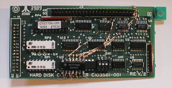
Upper side
|
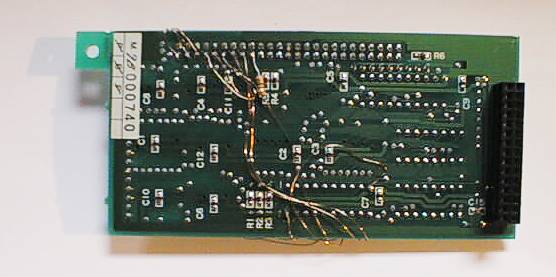
Lower side
|
|
|
SuperSTacy The cover does not fit:( | 31.10.01 maanke | Don't panic, it works (I didn't believe it myself:)
To fit the cover back on the STacy you have to break one of the dowel pins, which is
directly above the PAK, otherwise you will not get
the cover closed. With a PAK it fits very tight, if you
leave out the plate box. If you're unlucky like me and your cache RAMs that are under the
TOS ROMs are socketed you will not get the cover closed. I had to remove the sockets and solder
the RAMs directly to the PAK than it will fit.
I don't know if all PAK's have socketed cache RAMs,
if so I wish you much fun.;^)
Before reassembling everything you should put a piece of cardboard over the daughterbord,
because the underside of the keyboard is metal.
Some words about that what will remain, first we have the plate box , then the destroyed
68000, the harddisk and a screw, which was in the broken dowel pin. Don't try to screw this back
the old place because you will damage you're PAK!
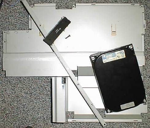
...that's what remaining.:)
Now you can reassemble you're STacy, remember be carefull when handling the
keyboard foil!!!
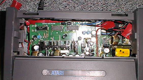
...the replaced PSU.
The reward you will get for your hard work is a fast and snappy STacy,
which brings fun again.
I hope you will enjoy this modification and are successful!
Have fun!
Marc-Antón Kehr
|
|
|
|
All pictures made with

Best viewed with

|